Register Grid
The register grid is where you'll spend most of your time in Client mode. This is where you read data, interpret values and write back to the device.
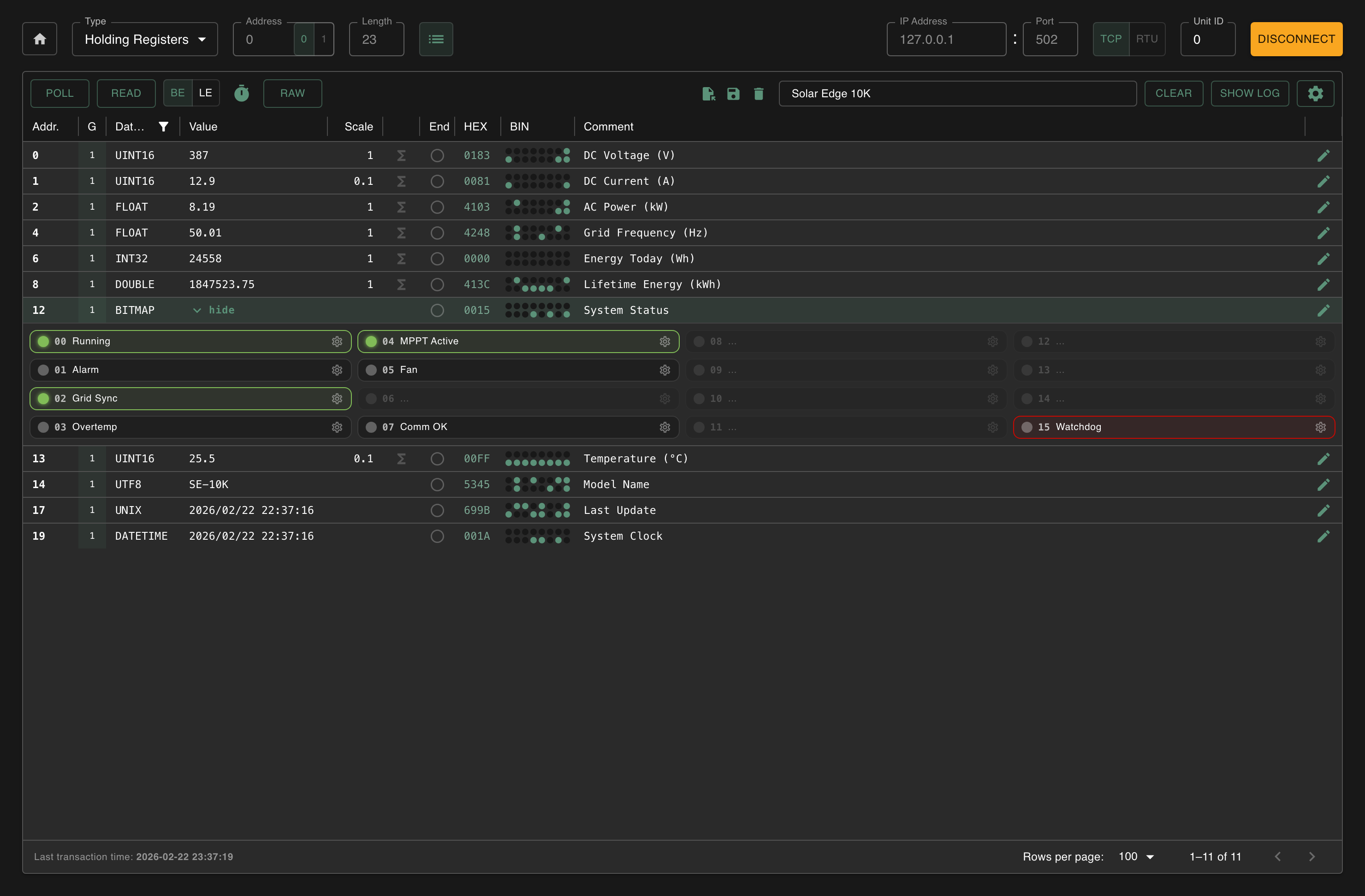
Reading registers
Before you can see data, you need to tell Modbux what to read:
- Choose the register type (Holding, Input, Coils or Discrete Inputs)
- Set the start address and length, e.g. address 0, length 23 to read the first 23 registers
- Click Read
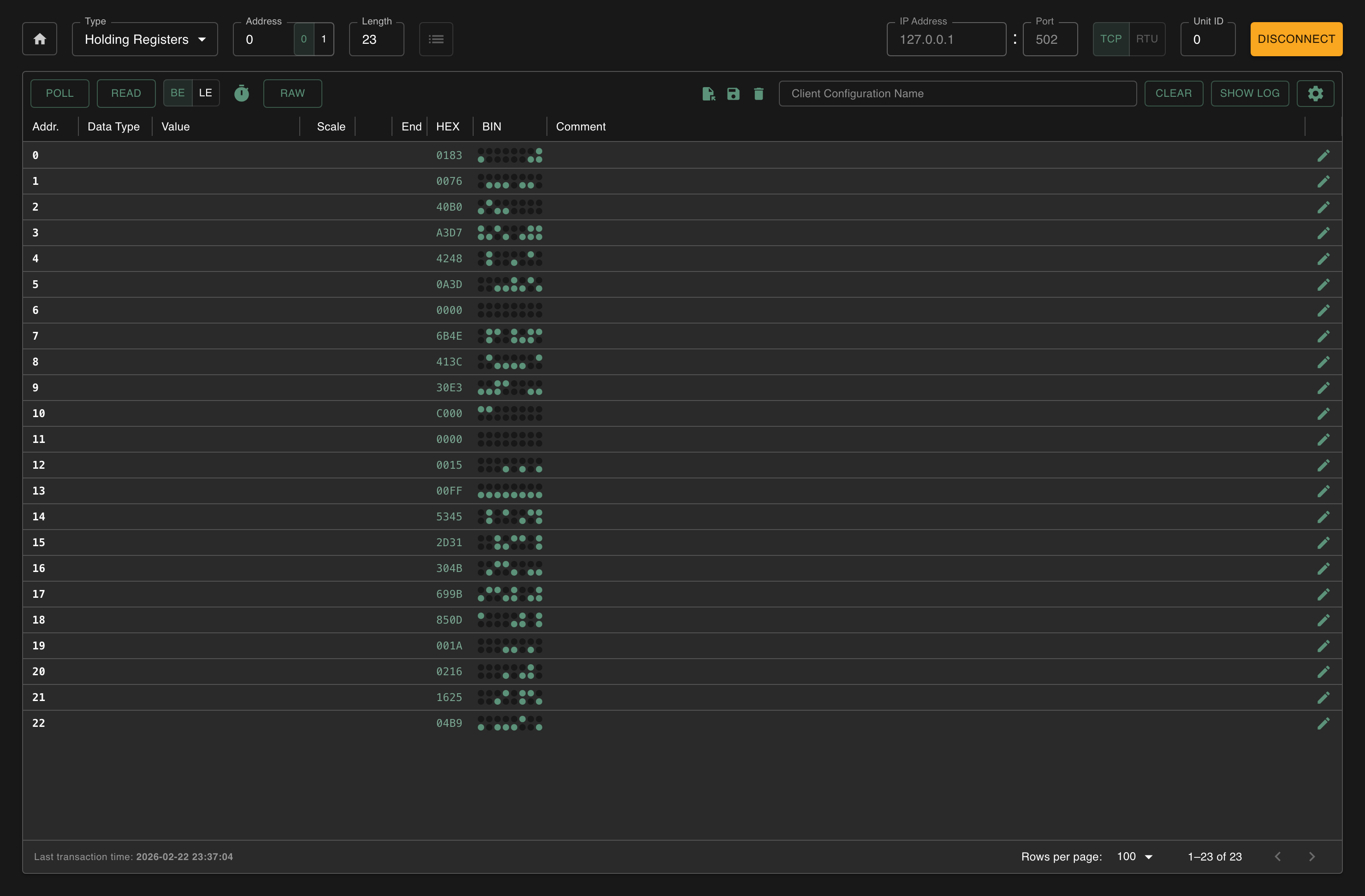
When working with multi-register data types (32-bit or 64-bit), make sure your length covers enough registers. A float needs 2 registers, a double needs 4.
Advanced Mode: see all data types at once
When you're reading a device for the first time and don't know which data types the registers use, turn on Advanced Mode via the cog icon in the toolbar. This shows int16, uint16, int32, uint32 and float interpretations as extra columns side by side, so you can immediately see which interpretation makes sense for each register.
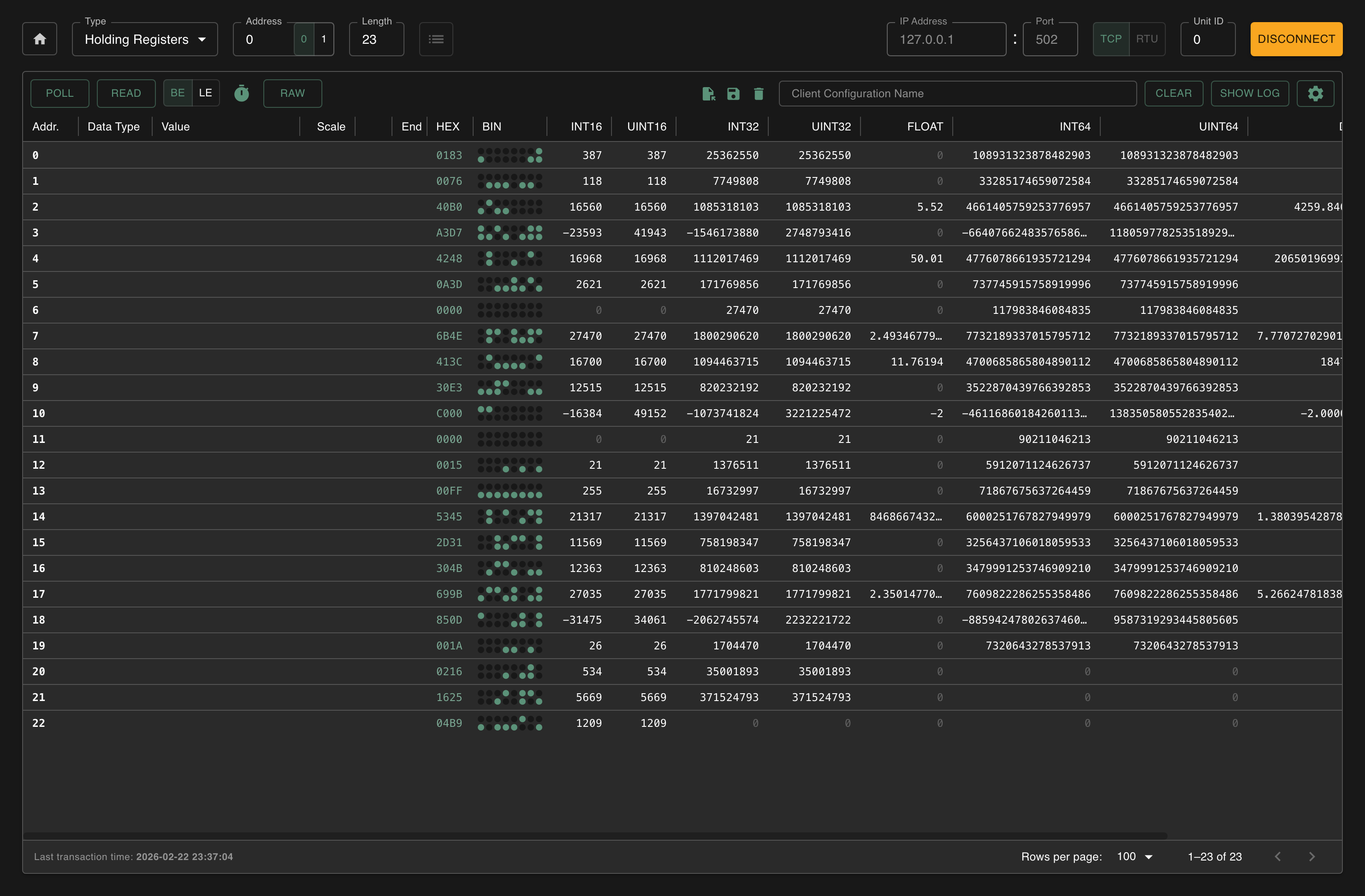
Keep in mind that multiple interpretations can look valid at the same time. A value like 250 fits in both int16 and int32, so you can't always tell from one read which type it actually is. Cross-reference with your device documentation, or watch how values change over time to narrow it down.
Enable 64-bit Mode from the same menu if you also need int64, uint64 and double columns.
Monitoring live data
Want to continuously track values, for example a temperature that's changing? Then use Poll:
- Click Poll in the toolbar
- Modbux now repeatedly reads the same registers at a fixed interval
- Click Poll again to stop
Adjust the interval and timeout via the clock icon. A lower interval gives faster updates, but more network traffic.
Read Configuration
The Read Configuration toggle (list icon in the register configuration area) changes how Modbux reads data. Instead of reading a continuous range from start address to length, it reads only the registers you've configured, automatically grouped into efficient read operations.
This is especially useful when your configured registers are spread across a wide address range. Without Read Configuration, you'd have to do multiple reads to cover the gaps between your registers. With it, Modbux only fetches the addresses that matter.
Group column
The "G" column shows which read group each register belongs to. Modbux groups contiguous addresses into efficient read operations. The group index, with alternating background tints, lets you see exactly how your reads are grouped.
Inline errors
When a read group fails (e.g. a Modbus exception or timeout), the error is displayed inline in the grid for that specific group. This way you can immediately see which group of addresses failed, while the other groups still show their data.
You can use the Group End toggle on individual registers to split a failing group into smaller ones. Modbux normally groups registers automatically for the most efficient reads, but by setting a group end you force a split at that point. This lets you binary-search for the problematic address: split the failing group in half, see which half fails, split that half again, and so on until you've pinpointed exactly which register is causing the error.
Writing registers
Writing is only possible to Holding Registers and Coils. Input Registers and Discrete Inputs are read-only by definition.
To write a value:
- Read the registers first so they appear in the grid
- Click the Write button on the row you want to modify
- Set the data type and the new value
- Choose FC6 (single register) or FC16 (multiple registers) and send
Writing is not possible while polling is active. Stop polling first, then write your value.
When you click the Write button, Modbux automatically switches to RAW mode so you can see the actual value you're about to overwrite.
Writing coils
Click the Write icon at the end of a coil row to open the write modal. The modal lets you choose the function code and set the value before writing.
- FC5 (Write Single Coil): toggle the coil between 0 and 1, then send.
- FC15 (Write Multiple Coils): shows toggles for all coil addresses starting from that row, so you can set multiple coils at once before sending.
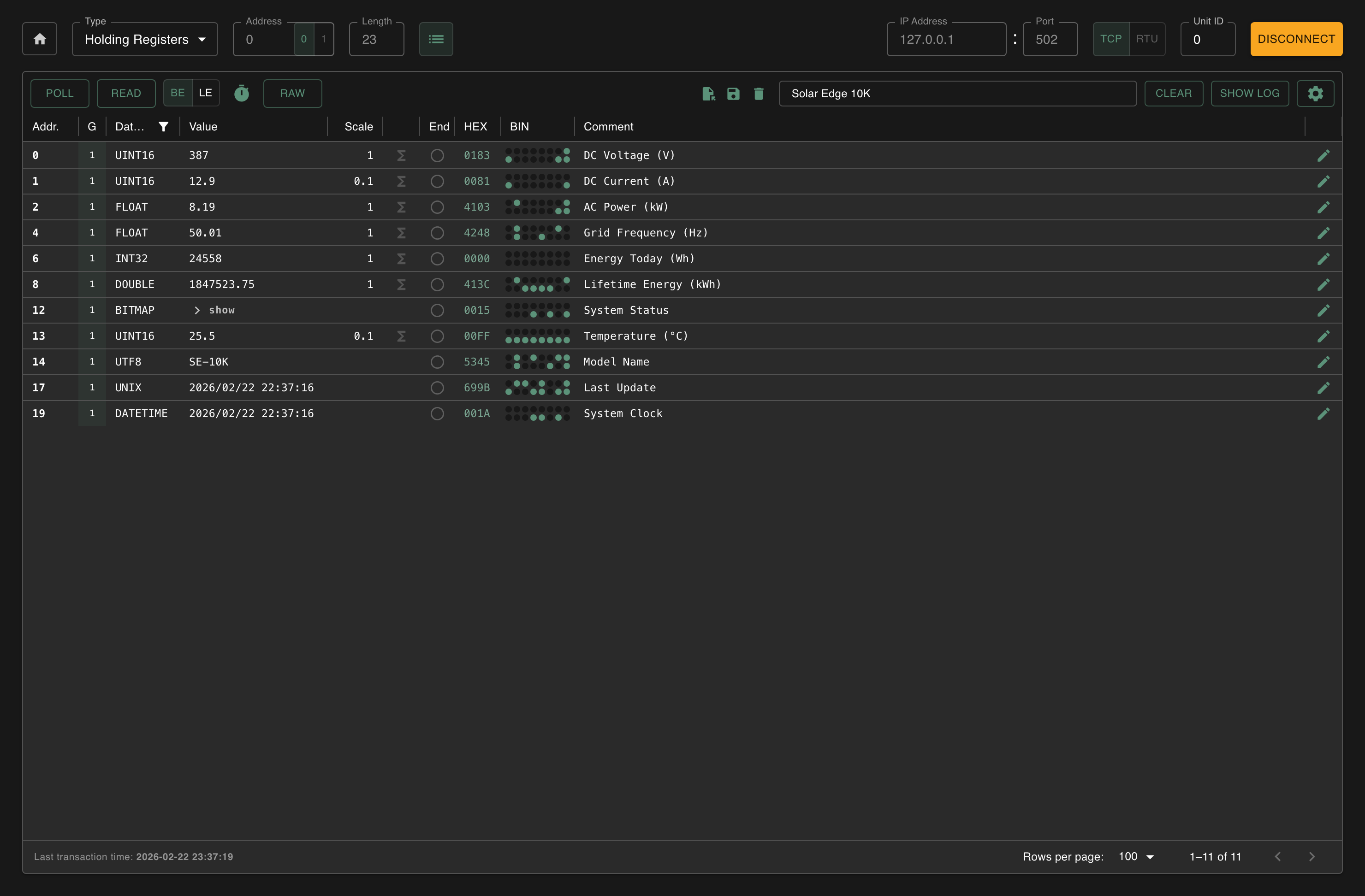
Setting data types
Raw Modbus data is always 16-bit. But the actual value can be anything: a temperature as float, a counter as uint32, or text as UTF-8. Modbux can interpret the raw bytes for you.
Click the Data Type cell of a register and choose the correct type:
Single register (16-bit): int16, uint16, bitmap
Two registers (32-bit): int32, uint32, float, unix (Unix timestamp)
Four registers (64-bit): int64, uint64, double, datetime (IEC 870-5)
Text: utf8, each register contains 2 ASCII characters. Modbux decodes consecutive registers as one string until it hits a register with a different data type set, or until there are no more registers in the read range.
The Converted Value column shows the interpreted value. Select float for two consecutive registers, for example, and you'll see the decimal value instead of two separate 16-bit numbers. Unix timestamps and datetime values are displayed as human-readable date/time strings.
Coils and Discrete Inputs are simple: each row shows one bit (0 or 1). No data type conversion needed.
The grid shows the address, the bit value, a comment field and (for coils) a write button.
Bitmap
When you set a register's data type to bitmap, an expandable detail panel appears below the register row. This panel shows all 16 bits of the register individually, each with:
- Toggle indicator: shows the current bit state; clickable to toggle when the register is writable (Holding Registers)
- Comment: an inline editable label for each bit (e.g. "Motor running", "Alarm active")
- Color: choose between default, warning or error to visually flag bit states
- Invert: flip the display logic (show "on" when the bit is 0)
Bitmap configuration (comments, colors and invert settings) persists when you save a client configuration file.


Word order (BE/LE)
When you use 32-bit or 64-bit data types, the value is split across multiple registers. The order of those registers (Big-Endian or Little-Endian) differs per device. If your values look like nonsense after setting the right data type, the word order is probably wrong.
Click the BE/LE toggle in the toolbar to switch. Big-Endian (the Modbus standard) puts the most significant word in the first register. Little-Endian reverses it. See Understanding Modbus for a detailed example.
The endianness setting is now included in client config files, so your word order preference is preserved when you save and load configurations.
RAW mode
Click RAW in the toolbar to ignore any configured scaling and interpolation. The value column shows the raw register value as-is.
Address base
Modbux uses 0-based protocol addresses by default. If your device documentation uses 1-based addressing, use the 0/1 toggle in register configuration to shift all displayed addresses by +1. This is a display-only change. The actual Modbus protocol addresses stay the same.
Scaling and interpolation
Often a device reports a raw value that you still need to convert. Modbux offers two ways:
Scaling
A simple multiplication. Click the Scaling cell and enter a factor.
Example: a device sends 234 for a temperature of 23.4°C. Set scaling to 0.1 and you'll see 23.4 in the Converted Value column.
Interpolation
For linear conversions with two reference points. Configure x1, y1, x2, y2 in the Interpolation cell.
Example: a sensor sends values from 0-65535 that correspond to 0-100%. Set: x1=0, y1=0, x2=65535, y2=100. A raw value of 32768 then becomes 50%.
Saving and loading configurations
You can save your complete register setup so you don't have to set it up again:
- Give your configuration a name in the name field
- Click the save icon
- Everything is saved: register types, addresses, data types, scaling, interpolation, comments, group-end markers, bitmap configuration and word order
To load a configuration, click the load icon and choose the file.
Configuration files are now versioned (v2 format with metadata). Old v1 configuration files are automatically migrated when loaded. No manual conversion needed.
Configurations saved in v2 cannot be opened in older versions of Modbux. Keep backups if you need backward compatibility.